Patented Apr. 3, 1928 1,664,436
United States Patent Office
Beatrice S. Tonnesen, of Chicago Illinois
This invention relates to flower holders. It is customary in connection with rose bowls and the like to place in the bowl a perforated block into which the stems of the flowers may be inserted for support. This arrangement while suited for short stemmed flowers is not adapted for long stemmed ones.It is an object, therefore, of the present 10 invention to provide a holder or support for long stemmed flowers.
Other and further important objects of this invention will be apparent from the disclosures in the accompanying drawings and the following specification.
The invention (in a preferred form) is illustrated on the drawings and hereinafter more fully described.
On the drawings: –
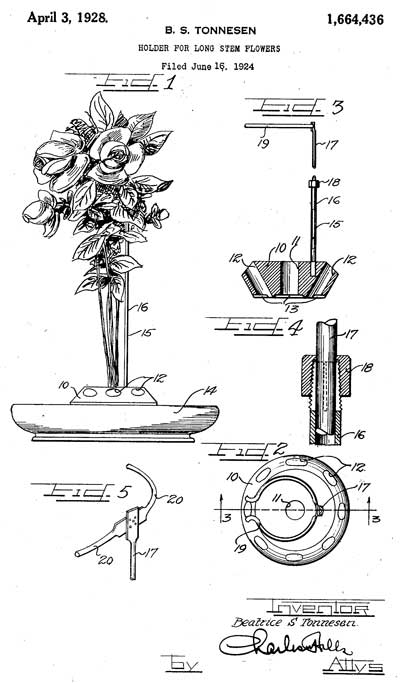
Figure 1 is a side elevation of a bowl with a flower holder constructed in accordance with the present invention.Figure 2 is a plan view of the holder.
Figure 3 is a section on the line 3-3 of Figure 2.
Figure 4 is a section through the tele¬scopic joint of the holder.
Figure 5 is a view of the upper part of the holder showing a modified form of stem encircling arms.
As shown on the drawings:¬ –
The holder comprises a base 10, preferably of iron or other heavy material, provided with a central aperture 11 and a series of upwardly and outwardly extending inclined apertures or passages 12 spaced therearound. The lower part of the base has recesses 13 formed therein to allow the water in the bowl 14 in which the holder is placed to pass freely in and out of these apertures.
Extending vertically upwards from an off center point of the base is an upright 15, preferably telescopic so that its height may be adjusted to suit the length of stem of the flowers to be supported. As shown, the lower half 16 of the upright is square at its lower end from frictional, rigid and non-rotatable engagement with a similarly shaped aperture in the base and tubular at its upper end into the open end of which extends a rod 17 forming the upper half of the upright. The top of the tube 16 is conical in form, threaded and slotted so that it may be compressed against the rod 17 to hold the latter in adjusted postion by tightening the union 18.
Get the full text of the legal description in PDF format here.